I/O & EtherCAT
Bu içerik henüz dilinizde mevcut değil.
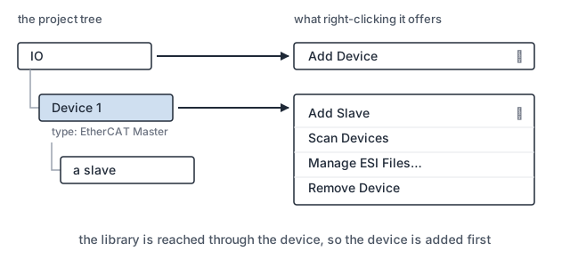
The drives and I/O of the machine are described, added and mapped here. A device on the bus is not yet a device your project can use: the master finds an address and an identity, and everything else comes from the vendor’s description of it.
Bringing a device in
Section titled “Bringing a device in”- Add the master. Right-click
IO, chooseAdd Device, and pickEtherCAT Masteras the type. The node carries the name you give it rather than the type, so the tree showsDevice 1and not what it is. Every slave is added under it, and the rest of this page happens on its context menu. - Import the vendor’s description. Right-click the master, choose
Manage ESI Files…, and useImport File…for a single file orImport Folder…for a vendor’s whole set. The same dialog opens fromManage ESI…insideAdd Slave, so a description you find you are missing does not send you back to the tree. - Add the slaves. Right-click the master and choose
Add Slave, then take the device from the library, which lists it under its vendor. A vendor you cannot find there is a vendor whose files you have not imported.Countadds several identical ones in one step.
Scan Devices, on the master and on the toolbar, reads what is actually on the wire instead.
A scanned device whose description is missing is still listed, and the scan window takes an
ESI for that row so you can bring it in without leaving the scan.
A device exists in the project only if its description does
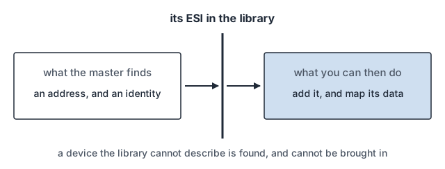
Section titled “A device exists in the project only if its description does”Step 2 above is not a formality. Nothing can be added or mapped until the vendor’s
description of the device is in the library. A device the library cannot describe is not
offered when you add one, and Scan Devices finds it on the wire but cannot bring it in.
A modular slave is described slot by slot
Section titled “A modular slave is described slot by slot”Some slaves are one fixed device. Others are a rack: a coupler with terminals behind it,
where the description declares slots rather than contents. Those carry a Slots tab, and
there you say what is in each one.
What a modular slave exchanges comes from the modules you place, not from the slave itself. Describe the rack short and the terminals you left out cannot be mapped, with nothing on the bus to say the description is wrong.
What is exchanged every cycle is what your logic can read
Section titled “What is exchanged every cycle is what your logic can read”A device can usually do more than the machine needs it to. The process data you assign is what the master reads and writes every cycle, and that is what becomes a variable to map. Process data that is not assigned is not on the bus at all.
The project carries its own copy of every ESI
Section titled “The project carries its own copy of every ESI”Each device in the project keeps two files and needs both:
| the device as configured | its address, and the process data your project maps |
| the vendor’s ESI | what the device is capable of: its object dictionary, its mailbox, distributed clocks and its modules |
An ESI is looked for in the project first, then in your library on this PC, then in what shipped with the Development System. Adding a device copies the file it matched into the project. The project’s copy wins, so the project builds the same way on a PC whose library holds a different revision, and a project that opens without one of its files names the ones it could not find.
Where to go next
Section titled “Where to go next”- Motion & NC: joining a drive to an axis, and gathering axes into a CNC.
- Linking: joining assigned process data to a variable your logic reads.
- PLC: the logic that reads those variables.
- The Project: what else travels with a project.